A printed circuit board is more than a flat surface holding electronic parts. Its copper traces carry signals and power, while its substrate provides support and insulation. The right PCB board depends on the device, the space available, and the electrical demands it must meet. A simple remote control has different needs from a compact medical monitor or an industrial controller.
This guide introduces common PCB types, including single-sided, double-sided, and multilayer boards. It also looks at rigid, flexible, and rigid-flex designs, which differ in how they bend and fit inside a product. These categories describe different features, so they can overlap: a flexible board may also use several conductive layers. The labels overlap. Understanding that distinction makes comparisons more useful.
When evaluating a board, consider its layer count, material, component density, operating environment, and manufacturing requirements. For example, a thick multilayer board can route many connections through a small area, while a flexible circuit can follow a curved enclosure. Neither option is automatically better. Trade-offs matter. Exact performance depends on the design and fabrication process, so a board’s name alone cannot confirm its suitability. The sections ahead explain what each type does, where it is commonly used, and which practical details deserve closer review before selection. Some choices are less tidy than a chart suggests; real products often combine constraints that do not fit one neat category.
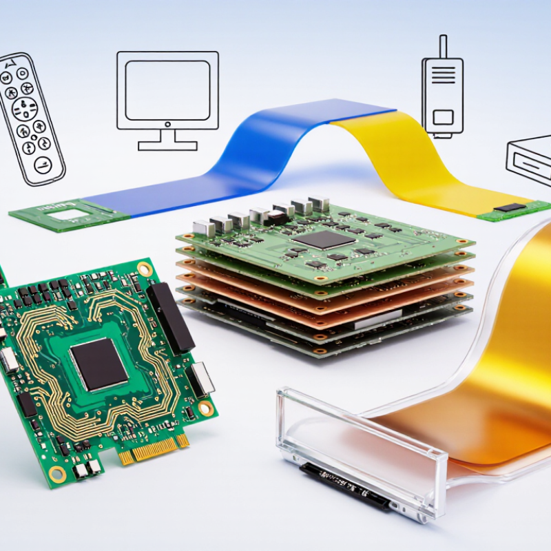
PCB types are often grouped by how many copper layers carry electrical paths. The copper sits on insulating material, and each layer serves as a routing surface. A single-sided board has copper on one face, with components usually mounted on that side. It suits simple circuits, such as basic controls or small lighting devices. Simple, but limited.
A double-sided board has copper on both faces. Plated holes, called vias, connect paths between them. This gives designers more routing space without greatly increasing board size. You may see this structure in power supplies, instruments, and compact equipment. Its success still depends on careful trace spacing and current planning.
Multilayer boards combine three or more copper layers, separated by insulating sheets and bonded into one stack. Common designs use four, six, or more layers. Inner layers can carry power or ground planes, while outer layers hold components and signal routes. This can reduce electromagnetic interference and support dense layouts, but fabrication and inspection become more demanding. More layers are not automatically better. A thicker stack may complicate heat flow, and poorly planned transitions can weaken signal quality. The layer count alone says little about reliability; copper thickness, material, via design, and operating conditions also matter. A sensible stack-up starts with the circuit’s real needs, not a larger number on a drawing.
PCB structure shapes how a device fits, bends, and withstands handling. Rigid boards use stiff laminate, often with copper layers separated by insulating material. They hold components firmly and suit flat assemblies such as control modules or power units. Their predictable shape supports inspection and automated assembly. That matters.
Flexible PCBs use thin polymer films, commonly polyimide, with patterned copper. They can fold around a camera module or pass through a narrow hinge area. Flex is not indestructible: repeated motion, sharp creases, and poor support can damage copper traces. Designers specify a bend radius and keep components away from moving zones. In practice, that radius may compete with the space available. Not always easy.
Rigid-flex combines stiff sections with flexible interconnects in one connected construction. Components sit on rigid islands, while flex regions can replace separate cables and connectors. This may reduce assembly steps and free space, but layer transitions need careful stack-up design. Copper balance, adhesive choice, and strain relief all affect reliability. A useful design review checks the actual motion path, not just the board outline. Even a small mismatch between the layout and enclosure can cause rubbing or concentrated strain.
| Comparison Dimension | Rigid PCB | Flexible PCB | Rigid-Flex PCB |
|---|---|---|---|
| Basic Structure | A solid, non-bending board made from one or more laminated layers. | A thin circuit built on a bendable film substrate. | A single interconnected assembly combining rigid sections with flexible circuit sections. |
| Common Base Materials | Glass-reinforced epoxy laminate, commonly FR-4; other laminates are used for specialized electrical or thermal needs. | Polyimide is widely used; polyester film is used in some less demanding applications. | Typically uses rigid laminates such as FR-4 alongside polyimide flex layers. |
| Mechanical Behavior | Maintains its shape during normal use and is not designed to flex. | Can bend or fold where the design allows; dynamic flexing requires a suitable stackup and bend design. | Rigid areas support components, while designated flex areas can bend to connect sections. |
| Typical Applications | Computers, control systems, power supplies, consumer electronics, and general-purpose electronic assemblies. | Cameras, wearables, compact devices, displays, and connections that must fit into limited or moving spaces. | Compact assemblies with multiple sections, such as cameras, medical equipment, aerospace systems, and other space-constrained electronics. |
| Assembly and Packaging | Components are mounted on a stable, flat board; cables or connectors may be needed between separate boards. | Can replace some wires or connectors and conform to curved or folded enclosures. | Can connect rigid component-mounting areas without separate cables or board-to-board connectors. |
| Main Advantages | Broad material and fabrication options, strong mechanical support, and often economical for conventional layouts. | Low profile, light weight, and freedom to fold or route circuits through confined spaces. | Combines component support with flexible interconnection and can reduce assembly parts and connection points. |
| Key Design Considerations | Board thickness, layer stackup, copper weight, thermal management, and mechanical support. | Bend radius, copper type and direction, layer stackup, coverlay, and strain relief at transitions. | Flex-zone bend requirements, rigid-to-flex transitions, stackup balance, component placement, and fabrication tolerances. |
| Relative Design and Manufacturing Complexity | Generally the simplest of the three for standard board designs. | Requires flex-specific materials and careful mechanical design. | Usually the most complex because rigid and flexible regions must be designed and fabricated as one assembly. |
Material choices, achievable layer counts, bend limits, and cost depend on the specific design and manufacturing process. Flexible sections should only bend as specified in the board design.
PCB boards are often classified by how components attach to the substrate. The main options are through-hole technology (THT), surface-mount technology (SMT), and mixed-technology assembly. Each choice affects board size, assembly steps, inspection, and repair. With THT, component leads pass through drilled holes and are soldered on the opposite side. A connector’s metal pins, visible beneath the board, make its joints easier to inspect and can provide strong mechanical support. THT may suit parts exposed to repeated plugging or vibration, but drilling takes space and adds processing time. Not always.
SMT places components directly onto pads on the board surface. Tiny resistors and capacitors can sit close together, enabling compact layouts and automated placement. The trade-off is that dense parts may be harder to inspect or replace by hand, especially when solder joints sit beneath a component. Mixed-technology boards combine both methods, perhaps using SMT for logic and THT for a heavy power connector. This can balance density with mechanical support, though it adds assembly coordination. Details matter. Pad design, soldering conditions, component shape, and expected loads all influence performance. A small connector can still loosen if its pads and mechanical anchors are poorly designed.
Specialized PCB designs solve different physical and electrical problems. Rigid boards suit stable, flat assemblies, while flexible circuits bend around hinges, sensors, and narrow enclosures. They can reduce connectors and save space. But repeated bending still requires careful testing; flexibility does not guarantee durability. Grand View Research valued the global flexible PCB market at USD 20.3 billion in 2023 and forecast a 10.1% compound annual growth rate from 2024 to 2030. That growth reflects demand across compact devices and other applications where wiring must move or fit tight contours.
Rigid-flex boards combine fixed sections with bendable links, helping equipment withstand vibration while reducing cable connections. High-density interconnect boards use finer traces and microvias to fit more connections into a small area, as seen in compact medical instruments and communication hardware. Metal-core boards move heat away from power components, making them useful in lighting and motor-control assemblies. Each design has a cost. More layers, tighter tolerances, or unusual materials can complicate fabrication and inspection. A dense layout may look efficient on screen, yet prove difficult to repair. Designers should check operating temperature, bend radius, vibration, and production limits before selecting a board type. The right choice depends on the real assembly, not just the schematic.
Rigid boards stay flat and support components firmly. Flexible boards use thin polymer films and bend around tight spaces. They still need careful handling.
It can pass through a narrow hinge or wrap around a camera module. Designers must control the bend radius and keep parts away from moving areas.
Not automatically. Repeated motion or a sharp crease can damage copper traces. Test the real movement path, not just the drawing.
It connects stiff component areas with flexible sections. This can replace cables and connectors, but layer transitions need careful design. Small layout mismatches matter.
Component leads pass through drilled holes and are soldered underneath. This can support a connector exposed to frequent plugging or vibration. Drilling takes space.
Components sit directly on surface pads, allowing compact layouts. Dense parts may be harder to inspect or replace by hand. A trade-off.
A board might use surface-mounted logic and a through-hole power connector. This balances compactness with mechanical support, though assembly becomes more involved.
High-density boards use fine traces and microvias to fit more connections into small instruments. Metal-core boards help move heat away from power components.
Consider temperature, vibration, bend radius, repair needs, and production limits. A neat schematic cannot show every enclosure rub or stress point.
| Cookie | Duration | Description |
|---|---|---|
| cookielawinfo-checkbox-analytics | 11 months | This cookie is set by GDPR Cookie Consent plugin. The cookie is used to store the user consent for the cookies in the category "Analytics". |
| cookielawinfo-checkbox-functional | 11 months | The cookie is set by GDPR cookie consent to record the user consent for the cookies in the category "Functional". |
| cookielawinfo-checkbox-necessary | 11 months | This cookie is set by GDPR Cookie Consent plugin. The cookies is used to store the user consent for the cookies in the category "Necessary". |
| cookielawinfo-checkbox-others | 11 months | This cookie is set by GDPR Cookie Consent plugin. The cookie is used to store the user consent for the cookies in the category "Other. |
| cookielawinfo-checkbox-performance | 11 months | This cookie is set by GDPR Cookie Consent plugin. The cookie is used to store the user consent for the cookies in the category "Performance". |
| viewed_cookie_policy | 11 months | The cookie is set by the GDPR Cookie Consent plugin and is used to store whether or not user has consented to the use of cookies. It does not store any personal data. |