Liquefied natural gas has changed the scale of modern energy logistics. GIIGNL’s 2024 Annual Report recorded approximately 404 million tonnes of global LNG trade in 2023. Each cargo depends on controlled heating, cooling, and pressure management. That is where an Lng Exchanger becomes essential.
John J. Carroll, an LNG process specialist and author of LNG: A Nontechnical Guide, states, “LNG is natural gas that has been cooled to approximately -260°F.” This extreme temperature explains the exchanger’s demanding role. It transfers heat without allowing the cold LNG stream to compromise equipment integrity. In a typical liquefaction plant, a multi-stream exchanger cools treated natural gas before storage. At a regasification terminal, seawater, glycol, or another heating medium restores the gas to usable conditions.
The principle sounds simple.
The hardware is not.
A brazed aluminum plate-fin unit may contain thousands of narrow passages. Fins increase surface area while keeping the equipment compact. Spiral-wound and shell-and-tube designs serve different flow rates, pressures, and maintenance requirements. Operators monitor temperature differences, pressure drop, vibration, and possible leakage. Even small contamination can reduce thermal performance or create operational risk.
The International Energy Agency’s Gas Market Report highlights continuing LNG infrastructure expansion and growing flexibility in global gas supply. That expansion increases attention on exchanger efficiency, reliability, and lifecycle cost. Yet a perfect design rarely exists. Material selection, weather conditions, startup procedures, and maintenance habits can change real performance. Understanding how an Lng Exchanger works therefore requires more than studying a diagram; it requires examining the complete process around it.
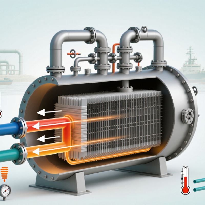
An LNG exchanger is a cryogenic heat-transfer device used in liquefied natural gas systems. It moves heat between two flowing fluids without allowing them to mix. During LNG production, natural gas must be cooled to about -162°C. At this temperature, the gas becomes a clear, low-volume liquid. The exchanger controls this demanding temperature change inside carefully designed passages.
Most LNG exchangers use metal surfaces, plates, or coiled tubes to transfer heat. Refrigerant may remove heat from natural gas, while warmer streams can vaporize LNG when needed. Insulation reduces unwanted heat gain from the surrounding air.
Pressure, flow rate, temperature difference, and material strength must remain within operating limits. A small leak can affect safety and product quality. That is why operators monitor sensors, valves, and pressure trends continuously.
In practice, exchanger performance is rarely perfect. Frost, contamination, or uneven flow may reduce efficiency over time.
Tips: Keep the exchanger clean and inspect insulation regularly. Compare inlet and outlet temperatures during each operating cycle. A growing temperature gap can indicate fouling or restricted flow. Never rely on one sensor alone. Verify unusual readings with a second instrument and follow the site’s approved maintenance procedure. Safety training matters, especially near cryogenic surfaces, where contact can cause severe injury.

An LNG exchanger transfers heat between liquefied natural gas and another fluid without mixing them. In a vaporizer, warmer seawater, air, or a heating medium supplies energy. LNG enters near -162°C and leaves as natural gas. In liquefaction service, the direction reverses. Cold refrigerant removes heat from treated gas, creating LNG.
The main component is the heat-transfer core. It may contain tubes, plates, or finned passages, depending on the duty. Tube walls separate LNG from the heating fluid. Plates provide compact flow channels. Headers and manifolds distribute fluid evenly across the core. Poor distribution can create cold spots and reduce performance. The shell, frame, and supports hold the assembly under pressure and thermal stress.
Insulation limits unwanted heat gain or loss, especially around cryogenic sections. Expansion joints absorb movement as metal contracts and expands. Temperature sensors, pressure gauges, flow meters, and control valves help operators monitor stable operation. Relief devices protect the exchanger from excessive pressure. Materials must remain tough at cryogenic temperatures, so aluminum alloys, stainless steel, and suitable low-temperature steels are commonly evaluated.
In practice, no exchanger is perfectly efficient. Frost, fouling, vibration, or uneven flow can change its performance. A design may look sound on paper but behave differently during startup. Careful inspection and gradual temperature changes matter. Small details matter greatly.
An LNG exchanger transfers heat without mixing the two fluids. In liquefaction, treated natural gas enters a cryogenic exchanger and meets a colder refrigerant stream. Heat moves through metal surfaces, while the gas temperature falls toward approximately -162°C. The refrigerant absorbs this energy, changes pressure, and returns through the cooling cycle.
The flow is usually counter-current. Warm gas travels one way; cold refrigerant travels the opposite way. This arrangement improves temperature efficiency along the exchanger’s length. In regasification, the process reverses. LNG absorbs heat from seawater, air, or a closed glycol circuit and becomes natural gas again. The outlet temperature must rise gradually. Thermal shock can damage equipment.
LNG demand makes this control important. GIIGNL’s 2024 Annual Report recorded global LNG trade at about 404.3 million tonnes in 2023. The IEA’s Gas 2024 report also recorded global gas demand growth of roughly 2.5% that year. More cargoes require reliable heat transfer under severe temperature differences.
Operators monitor pressure, flow rate, vibration, and temperature profiles continuously. A tiny performance loss can indicate fouling, maldistribution, or a seal problem. Small leaks matter. In practice, exchanger models are useful but imperfect. Weather, feed-gas composition, and startup conditions can shift the real result. Engineers therefore compare live measurements with design values before changing operating settings.
An LNG exchanger transfers heat without mixing the working fluids. It helps cool natural gas into a liquid or warm LNG back into gas. During operation, temperature differences can become extreme. Materials, pressure, and cleanliness therefore matter greatly. A small design error may create frost, pressure loss, or uneven flow.
Plate-fin exchangers are widely used inside LNG cold boxes. They contain stacked aluminum passages with fins that provide a large heat-transfer area. Their compact structure suits cryogenic service, but blocked passages can be difficult to inspect. Shell-and-tube exchangers are also common, especially in LNG vaporizers. One fluid flows through tubes while another surrounds them. This arrangement is sturdy and easier to maintain, although it usually needs more space.
Spiral-wound exchangers handle large LNG flows in many liquefaction systems. Their coiled tubes support efficient heat transfer and tolerate demanding temperature changes. Printed circuit heat exchangers offer another compact option for high-pressure duties. They use etched metal channels joined into a solid block. Their small size is attractive, but repair can be complicated. In field work, exchanger selection depends on flow rate, pressure, temperature range, and maintenance access. No type is perfect. Engineers must check the full process, not only the exchanger’s advertised efficiency.
LNG heat exchangers transfer heat between process streams to cool natural gas into a liquid or warm LNG back into gas. The chart compares representative minimum service temperatures commonly associated with major exchanger types used in LNG systems.
Plate-fin and spiral-wound exchangers are widely used for deep cryogenic duties near LNG temperatures. Shell-and-tube exchangers are common for precooling, vaporization, and reboiler services, while printed circuit heat exchangers are selected when compactness and high-pressure performance are important. Actual limits depend on materials, pressure, fluid composition, and detailed equipment design.
An LNG exchanger transfers heat between liquefied natural gas and a warmer or colder process stream. Its duty is simple in principle: control temperature without mixing fluids. In practice, performance depends on several connected factors. The temperature difference across the exchanger sets the driving force. A small approach temperature can improve efficiency, but it demands greater surface area and tighter control. Flow rate matters too. If LNG moves too quickly, pressure drop may rise and residence time may fall. If flow is too low, uneven distribution can create cold spots and unstable operation.
LNG composition changes the heat load. Methane-rich streams behave differently from feeds containing more ethane, nitrogen, or heavier hydrocarbons. Pressure also affects boiling behavior and outlet temperature. Operators should track inlet pressure, outlet pressure, temperature profiles, and actual flow readings together. One reading rarely tells the whole story. Fouling, moisture, and solid formation can reduce heat transfer or restrict channels. Even a thin deposit matters in narrow passages. Material selection is critical because cryogenic temperatures can cause contraction, brittleness, or seal leakage.
Control valves and sensors influence stability as much as exchanger geometry. A slow valve response may produce temperature swings during loading or startup. Insulation quality and ambient conditions also affect measured duty. During field checks, technicians often compare current pressure drop with clean-condition records. That comparison can reveal gradual fouling before capacity visibly declines. However, records may be incomplete or sensors may drift. This is where judgment becomes necessary. A simplified calculation can look convincing while missing two-phase flow, maldistribution, or changing feed composition. Performance reviews should combine design data, live measurements, inspection findings, and maintenance history. Small inconsistencies deserve attention.
A technical overview of LNG heat-exchanger functions, operating principles, performance indicators, and key design factors.
| Dimension | Technical Description | Typical Data or Range | Effect on LNG Exchanger Performance |
|---|---|---|---|
| Definition | An LNG exchanger transfers heat between liquefied natural gas and another fluid without directly mixing the two streams. | Common duties include liquefaction, LNG vaporization, boil-off-gas handling, and subcooling. | The duty determines the exchanger configuration, materials, temperature approach, pressure rating, and allowable fluid velocity. |
| Basic operating principle | Heat flows through a separating wall from the warmer stream to the colder stream. The streams normally pass through alternating channels, tubes, or coils. | Counter-current flow is widely used because it can achieve a smaller temperature difference and higher thermal effectiveness than co-current flow. | A smaller temperature approach generally improves heat recovery but may increase exchanger size, control sensitivity, and design complexity. |
| Main cryogenic heat exchanger | Cools and condenses treated natural gas by transferring heat to a colder refrigerant or returning low-temperature process stream. | Natural gas is typically cooled to approximately −150°C to −160°C during LNG production, depending on pressure and composition. | Stable temperature profiles and balanced refrigerant distribution are essential for achieving the target LNG temperature and production rate. |
| LNG vaporizer | Receives LNG at cryogenic temperature and vaporizes it into natural gas for pipeline, industrial, or power-generation use. | Methane boils at approximately −161.5°C at atmospheric pressure; actual LNG vaporization temperature varies with pressure and composition. | Heat-source temperature, LNG flow rate, outlet-gas temperature, and ice or hydrate control directly affect capacity and reliability. |
| Common exchanger constructions | Frequently used constructions include plate-fin, spiral-wound, shell-and-tube, printed-circuit, and finned-tube designs. | Plate-fin and spiral-wound designs are common for cryogenic process service; shell-and-tube and open-rack designs are widely used for vaporization duties. | Construction affects allowable pressure difference, thermal effectiveness, cleanability, footprint, repair method, and resistance to thermal cycling. |
| Heat-transfer duty | The required heat-transfer rate is the amount of energy removed from or added to the process stream per unit time. | Q = ṁ × Δh, where Q is heat duty, ṁ is mass flow rate, and Δh is the specific enthalpy change. | Higher flow rate or a larger enthalpy change requires more heat-transfer area, greater utility flow, or both. |
| Temperature approach | The temperature approach is the difference between the hot-stream and cold-stream temperatures at a selected exchanger end. | The required approach is application-specific and is often only a few degrees to several tens of degrees Celsius. | A smaller approach increases the required heat-transfer area and may reduce the available driving force, especially near a pinch point. |
| Overall heat-transfer coefficient | The overall coefficient combines convection on both sides, wall conduction, fouling, and contact resistance. | Q = U × A × ΔTlm, where U is the overall coefficient, A is area, and ΔTlm is the log-mean temperature difference. | Lower U caused by fouling, poor distribution, gas pockets, or low velocity reduces capacity and increases the required surface area. |
| Fluid composition | LNG is primarily methane but can contain ethane, propane, nitrogen, and small amounts of other components after treatment. | The methane-rich composition affects boiling temperature, density, viscosity, enthalpy, and phase-equilibrium behavior. | Changes in composition can shift the temperature profile, alter vaporization duty, and increase the risk of two-phase maldistribution. |
| Pressure and pressure drop | Operating pressure influences boiling point, fluid density, phase equilibrium, and the mechanical design of the exchanger. | Allowable pressure drop is set by the process design; excessive pressure loss can reduce downstream pressure or increase pumping and compression requirements. | Higher velocity can improve heat transfer but usually increases pressure drop, vibration risk, and erosion potential. |
| Flow arrangement and distribution | Parallel channels, headers, manifolds, and passes must distribute single-phase or two-phase flow evenly across the active area. | Good distribution minimizes local hot spots, cold spots, dry-out, flooding, and uneven pressure drop. | Maldistribution lowers effective heat-transfer area and can cause local thermal stress or unstable outlet conditions. |
| Fouling, blockage, and contamination | Moisture, carbon dioxide, heavy hydrocarbons, corrosion products, or biological growth in the utility side can restrict flow or form deposits. | Cryogenic pretreatment is required to remove water and carbon dioxide that could freeze or form solids at low temperature. | Deposits increase thermal resistance and pressure drop; solid formation can block passages and force an unplanned shutdown. |
| Material selection | Materials must retain toughness and dimensional stability at cryogenic temperatures and withstand the operating pressure and fluid chemistry. | Aluminum alloys and austenitic stainless steels are commonly selected for cryogenic heat-transfer surfaces, subject to design requirements. | Inappropriate materials may suffer brittle fracture, corrosion, leakage, or excessive thermal-expansion stress. |
| Thermal cycling | Startup, shutdown, defrosting, and load changes repeatedly move exchanger components between ambient and cryogenic temperatures. | Thermal expansion and contraction occur at different rates in walls, fins, tubes, headers, and supports. | Frequent or rapid cycling can produce fatigue, seal damage, leakage, and loss of thermal performance. |
| Performance indicators | Performance is evaluated using thermal duty, outlet temperatures, approach temperature, pressure drop, flow stability, and exchanger effectiveness. | Effectiveness = actual heat transfer ÷ maximum possible heat transfer for the specified inlet conditions. | A sustained decline in effectiveness with rising pressure drop is a common indication of fouling, blockage, maldistribution, or changing operating conditions. |
| Monitoring and maintenance | Operators commonly track inlet and outlet temperatures, flow rates, pressure differences, utility conditions, gas composition, and leakage indications. | Trend analysis compares current values with clean or design-condition baselines rather than relying on a single measurement. | Early detection supports cleaning, defrosting, flow redistribution, control adjustment, or inspection before performance loss becomes severe. |
| Cookie | Duration | Description |
|---|---|---|
| cookielawinfo-checkbox-analytics | 11 months | This cookie is set by GDPR Cookie Consent plugin. The cookie is used to store the user consent for the cookies in the category "Analytics". |
| cookielawinfo-checkbox-functional | 11 months | The cookie is set by GDPR cookie consent to record the user consent for the cookies in the category "Functional". |
| cookielawinfo-checkbox-necessary | 11 months | This cookie is set by GDPR Cookie Consent plugin. The cookies is used to store the user consent for the cookies in the category "Necessary". |
| cookielawinfo-checkbox-others | 11 months | This cookie is set by GDPR Cookie Consent plugin. The cookie is used to store the user consent for the cookies in the category "Other. |
| cookielawinfo-checkbox-performance | 11 months | This cookie is set by GDPR Cookie Consent plugin. The cookie is used to store the user consent for the cookies in the category "Performance". |
| viewed_cookie_policy | 11 months | The cookie is set by the GDPR Cookie Consent plugin and is used to store whether or not user has consented to the use of cookies. It does not store any personal data. |