Why Is OPGW Used in Transmission Lines?
Modern transmission networks must carry more electricity while surviving lightning, wind, pollution, and growing renewable generation. The International Energy Agency’s Electricity 2024 report expects global electricity demand to keep rising through 2026. Meanwhile, IRENA reported 473 GW of new renewable capacity added worldwide in 2023. These trends place greater pressure on existing corridors and grid reliability.
Opgw In Transmission Line applications address two infrastructure needs with one overhead component. Optical Ground Wire combines a metallic shield wire with fiber-optic cores. The metallic layer intercepts lightning and carries fault current. The fibers support high-speed communication, protection signals, condition monitoring, and utility telecommunications. This arrangement can reduce the need for separate communication cables and additional structures. That matters where right-of-way space is limited.
The design is practical, but not effortless. Engineers must match optical fiber count, short-circuit capacity, sag, span length, and installation tension. IEEE 1138 provides guidance for OPGW construction and testing, while IEC 60794 addresses optical-fiber cable requirements. Field experience also shows that damaged strands, poor grounding, or incorrect fittings can undermine a well-designed system. Small details matter.
According to CIGRE technical guidance, reliable overhead-line performance depends on coordinated mechanical, electrical, and optical design. OPGW can improve fault communication and support faster protection decisions. It may also create valuable data pathways for digital substations. However, it is not a magic solution. Utilities still need inspection plans, accurate asset records, and trained crews. The real question is not simply why OPGW is used, but how its design fits the line’s risks, operating voltage, and future communication demands.
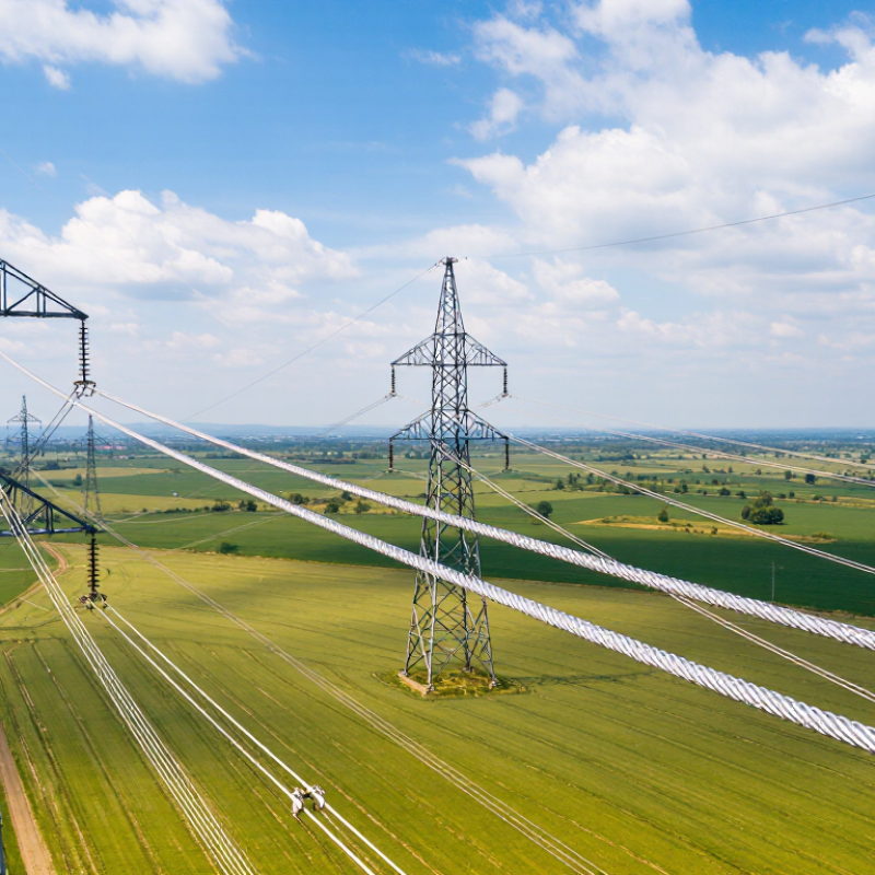
OPGW Structure: 24–48 Optical Fibers Inside a Lightning-Shielding Wire
Why Is OPGW Used in Transmission Lines?
OPGW combines two jobs in one overhead conductor. Its outer metallic strands intercept lightning above the phase conductors. Its protected optical fibers carry control, protection, and operational data. A typical design contains 24–48 optical fibers inside a central stainless-steel tube. Some designs use loose tubes, while others use a stranded configuration.
The fiber core does not carry lightning current. The surrounding aluminum-alloy or galvanized steel wires do. During a storm, these wires provide a low-impedance path toward grounded towers.
Inside the cable, the fibers remain electrically nonconductive and resist electromagnetic interference. This separation matters when protection relays must exchange trip signals within milliseconds.
The International Energy Agency reported in Electricity Grids and Secure Energy Transitions that global grid networks may need to expand or be replaced across more than 80 million kilometers by 2040. That scale increases the value of integrated communication infrastructure.
OPGW can support line differential protection, fault-location systems, and substation voice or data links without adding a separate aerial telecom cable.
IEC 60794-4-10 also addresses OPGW cable requirements and testing.
The 24–48-fiber range is practical, not universal. Fiber count depends on span length, short-circuit current, sag limits, and future communication demand. I would not select OPGW from fiber count alone.
A field inspection must also check tower grounding, wind loading, vibration, and splice-closure access. Small design shortcuts can become expensive maintenance problems.
Grounding Function: Handling 20–40 kA Short-Circuit Currents
Why Is OPGW Used in Transmission Lines?
OPGW combines optical fibers with a metallic overhead ground wire. During a fault, it provides a controlled path for lightning and short-circuit current. In many transmission systems, this path must withstand 20–40 kA for a specified time. That is serious heat. The conductor can experience rapid temperature rise, magnetic forces, and mechanical stress. Its design depends on short-circuit duration, tower spacing, fault current, and grounding resistance. A cable that looks adequate on paper may perform poorly if tower earthing is neglected.
Engineers check the OPGW’s ampacity, fault-current withstand rating, sag, and fittings before installation. They also inspect bonding points and downleads in the field. Poor connections can create hot spots, arcing, or unexpected current paths. The OPGW must protect the line while preserving its communication fibers. This dual role makes testing important. However, a 20–40 kA figure is not universal. Actual current varies with the network and fault location. That detail is easy to overlook.
Tips: Confirm the calculated fault current and clearing time first. Check every joint for tight, corrosion-resistant contact. Measure tower grounding resistance during commissioning and after major maintenance. Keep fiber attenuation records too. Small details matter.
Design Selection: Matching 40–150 kN Rated Tension to 110–1,000 kV Lines
Why Is OPGW Used in Transmission Lines?
Selecting OPGW for a 110–1,000 kV line is not a voltage-only decision. A 40 kN cable may suit a short, lightly loaded span. Longer spans, severe wind, or heavy ice can require 80, 120, or 150 kN designs. IEC 60826:2017 requires site-specific climatic loading, including wind, ice, and temperature effects. These forces directly influence sag, clearance, and tower loading.
The rated tension must match the complete mechanical system. Engineers usually check everyday tension, maximum tension, creep, vibration, and short-circuit heating. IEC 60794-4-10 also addresses OPGW construction and performance testing. Fault-current capacity matters because the metallic layers must carry current without damaging the optical fibers. A 500 kV line may need a stronger OPGW, but not simply because its voltage is higher. Span length and local weather can matter more.
Field assessments often expose the weak assumption: choosing the highest tensile rating is not automatically safer. Excessive strength can increase weight, tower reactions, installation difficulty, and cost. IEEE 1138-2021 emphasizes mechanical and electrical qualification for OPGW systems. I would compare calculated sag with actual tower geometry, then review installation records and historical storm data. The first selection is rarely perfect. Small errors become visible at the dead-end structure.
Installation Factors: Managing Sag, Vibration, Splicing, and Fiber Loss Limits
OPGW combines a transmission line’s grounding function with a protected fiber link. During installation, sag must be calculated carefully. Excessive sag can reduce ground clearance, while excessive tension can damage the cable or tower fittings. Engineers should check span length, temperature, wind, ice, and pulling tension before stringing. A line that looks safe during cool weather may sag noticeably in summer. Keep it practical.
Vibration also deserves close attention. Wind can create small, repeated movements that fatigue wires near clamps and suspension points. Install suitable vibration control devices according to the span and local exposure. Placement matters. A device installed too far from the correct point may provide limited protection. Small movements matter. Field crews should inspect clamps, bonding connections, and tower hardware after initial operation. Some installation assumptions are simply wrong in real terrain.
Splicing requires equal care because fiber performance can be lost inside a poorly prepared closure. Keep fibers clean, protect bend radius, and secure each splice against moisture and movement. Technicians should record splice loss and use OTDR testing to identify reflections, breaks, or abnormal attenuation. The complete link must remain within its calculated loss budget, including connectors, splices, and future repair allowance. Numbers can expose mistakes. If results exceed the limit, rework is safer than accepting a marginal connection. Even experienced teams should review the installation record before energizing the line.

