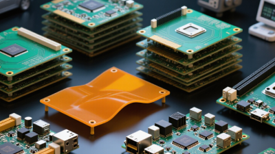
A PCB prototype is the first physical version of a printed circuit board design. It converts schematics, footprints, and routing decisions into something engineers can touch, inspect, and test. Under a microscope, a small solder bridge or uneven via can reveal a serious design weakness.
The need is growing. Prismark’s 2024 PCB Industry Forecast places the global PCB market above US$80 billion, reflecting the scale and complexity of modern electronics production. IPC’s 2024 electronics industry research also highlights continuing pressure on manufacturers to improve reliability, speed, and supply-chain resilience. A carefully built pcb prototype supports those goals before expensive tooling and mass production begin.
PCB technologist Happy Holden has described the printed circuit board as “the foundation of the electronics industry.” That foundation must be tested physically, not trusted only on a screen. A prototype can expose thermal hotspots, connector interference, weak solder joints, electromagnetic noise, or assembly delays. It can also show that a theoretically elegant layout is awkward for technicians.
That is the practical value.
A pcb prototype reduces uncertainty. It allows engineers to measure voltage, temperature, signal integrity, and mechanical fit under realistic conditions. Design teams can then revise the board while changes remain affordable. However, one prototype does not prove production readiness. That assumption is easy to make, and often wrong.
Reliable development combines prototype testing with design-for-manufacturing reviews, documented inspection, and repeatable measurements. The process may feel slower at first. In practice, it often prevents the much slower failure of a full production run.
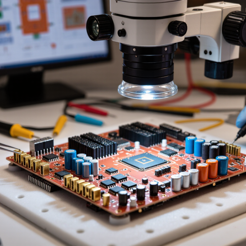
A PCB prototype is a physical trial version of a printed circuit board. It converts a schematic into a board that engineers can assemble, power, and inspect. The prototype reveals practical issues that software may miss, such as tight component spacing, weak solder joints, or difficult test access. According to Fortune Business Insights’ 2024 market report, the global PCB market was valued at about USD 89 billion in 2023. That scale shows why early design verification matters. Small layout errors can become expensive production problems.
A prototype usually includes the selected substrate, copper layers, drilled holes, surface finish, and required components. Engineers compare its performance against electrical, thermal, and mechanical requirements. IPC-2221 provides widely used guidance for PCB design, including spacing, materials, and reliability considerations. Still, a prototype is not proof of final success. A board may pass a bench test but fail after vibration, heat cycling, or repeated assembly. That uncomfortable gap needs attention. Good documentation records test conditions, revisions, and every unexpected result.
Tips: Test power delivery before full assembly. Mark probe points on the layout. Leave room for rework. Review thermal paths with real measurements, not assumptions. A cheaper prototype can save weeks later, but rushing the first revision often creates avoidable doubt.
A PCB prototype is a working sample that turns a circuit design into physical evidence. Its main function is verification. Engineers can measure voltage, signal integrity, current draw, and heat before production begins. They can also check connector access, mounting holes, enclosure clearance, and component spacing. Small details matter.
A prototype also tests manufacturability. It can reveal narrow traces, weak solder joints, difficult inspection points, or parts that cannot be placed consistently. IPC’s 2024 electronics industry outlook highlights continuing pressure from supply-chain risk, cost control, and product complexity. Early physical testing helps teams respond to these pressures with fewer surprises. A 2024 Fortune Business Insights report estimates the global PCB market at USD 89.7 billion in 2023, with strong growth expected through 2032. That scale makes preventable design errors expensive.
The prototype supports firmware development, functional testing, and early safety reviews. Test points can be added before access becomes difficult. Thermal cameras may expose a hot regulator that simulations missed. The board may fit poorly. That is useful evidence, not failure. In practice, one prototype rarely answers every question, so engineers often revise the layout and build another version. This extra cycle feels inefficient, but it can protect production schedules, tooling costs, and field reliability. A prototype is not the final product. It is a disciplined way to discover what the design still misunderstands.
A PCB prototype is an early physical version of a circuit board. It turns a schematic into something engineers can power, inspect, and test. In practical development, prototypes expose problems that software simulations often miss. A connector may sit too close to an enclosure wall. A sensor may produce unstable readings near a switching circuit. Small details matter.
A proof-of-concept prototype checks whether the core circuit works. It may use fewer features and simpler routing. A functional prototype includes the intended components, interfaces, and firmware connections. This version supports realistic testing, such as measuring voltage noise during motor startup. A form-and-fit prototype focuses on physical space. It confirms mounting holes, board thickness, connector access, and enclosure clearance. It may not contain every working circuit.
An engineering validation prototype is closer to the final design. It uses selected materials, controlled assembly, and documented test conditions. Engineers may review signal integrity, thermal behavior, solder quality, and manufacturability. A production-intent prototype goes further. It reflects the planned stack-up, component placement, and assembly process. This helps reveal supply, inspection, and yield risks before volume production.
Choosing one type depends on the question being asked. Is the circuit possible, usable, or ready to manufacture? A prototype can pass electrical tests and still fail inside a hot enclosure. That is an easy mistake to underestimate. Clear test records, repeat measurements, and independent design reviews improve reliability. Yet no prototype removes every risk. Each version should answer a specific engineering question.
A PCB prototype is a working sample built before full production. It turns a circuit idea into a physical board for inspection and testing. Development begins with clear electrical requirements, operating conditions, and enclosure limits. Engineers create a schematic, select suitable components, and check power paths carefully. A small mistake here can affect the entire design.
The schematic becomes a board layout with copper traces, solder pads, and mounting holes. Engineers control trace width, spacing, heat flow, and signal quality. Design-rule checks can identify unsafe gaps or disconnected nets. However, software does not catch every practical problem. The first layout is rarely perfect. A connector may sit too close to the case wall. A technician then prepares manufacturing files and assembly instructions. After fabrication, the prototype is inspected, powered gradually, and tested under realistic loads. Measurements should be recorded, not remembered. Failed tests often reveal weak assumptions about heat, noise, or component access. One revision may fix several issues, while another may expose a deeper design concern.
Tips: Label test points clearly. Keep critical components accessible. Compare the assembled board with the approved files. Photograph unusual defects before rework. Leave space for probing and airflow. Ask an experienced engineer to review the layout before fabrication. Small oversights become expensive later.
| Development Stage | Main Purpose | Typical Inputs | Key Outputs | Common Validation Activities | Problems Detected |
|---|---|---|---|---|---|
| 1. Requirements Definition | Translate product functions into electrical, mechanical, environmental, and compliance requirements. | System specifications, interface requirements, power targets, enclosure constraints, operating conditions. | Approved requirements document and preliminary block diagram. | Requirement reviews, interface checks, power-budget analysis. | Missing functions, incompatible interfaces, unrealistic power or size targets. |
| 2. Schematic Design | Define how components and electrical nets are connected. | Circuit architecture, component specifications, reference designs, interface standards. | Schematic diagrams, netlist, preliminary bill of materials. | Electrical rule checks, power-tree review, signal-integrity and component-rating review. | Incorrect connections, missing pull-ups, insufficient voltage ratings, unstable power rails. |
| 3. PCB Layout | Convert the schematic into a manufacturable physical board design. | Schematic, board outline, layer stackup, design rules, thermal and mechanical constraints. | Placed and routed PCB layout, fabrication drawings, assembly drawings. | Design-rule checking, clearance review, return-path analysis, thermal review, 3D fit check. | Routing congestion, inadequate clearances, electromagnetic interference risks, mechanical interference. |
| 4. Prototype Fabrication | Produce a physical board for engineering evaluation. | Gerber or equivalent fabrication files, drill files, stackup, material and finish requirements. | Unpopulated printed circuit boards. | Visual inspection, dimensional checks, continuity testing, layer and finish verification. | Open or short circuits, incorrect dimensions, damaged pads, fabrication defects. |
| 5. Component Assembly | Install electronic components on the prototype board. | Bill of materials, placement files, assembly drawings, component samples. | Populated PCB assemblies. | Visual inspection, solder-joint inspection, automated optical inspection where available. | Wrong part placement, polarity errors, solder bridges, insufficient solder, missing components. |
| 6. Bring-Up and Debugging | Power the board safely and confirm basic operation before full testing. | Assembled prototype, test points, firmware, laboratory instruments, bring-up procedure. | Initial test results, debug records, hardware or firmware change list. | Current-limited power-up, voltage measurements, clock checks, reset checks, interface tests. | Excess current, overheating, unstable rails, boot failures, incorrect logic levels. |
| 7. Functional and Performance Testing | Determine whether the prototype meets its intended electrical and operational requirements. | Approved requirements, test plan, firmware, test fixtures, measurement equipment. | Measured performance data and verification report. | Input/output testing, communication testing, load testing, thermal measurements, power-consumption measurement. | Timing failures, communication errors, inadequate throughput, excessive heat, battery-life issues. |
| 8. Design Revision | Correct identified issues and improve manufacturability, reliability, or performance. | Test failures, user feedback, engineering-change records, updated component availability information. | Updated schematic, layout, bill of materials, firmware, and revision history. | Regression testing, design reviews, tolerance analysis, manufacturability review. | Recurring failures, difficult assembly, component obsolescence, excessive production cost. |
| 9. Pre-Production Readiness | Confirm that the design is ready for controlled production and formal compliance work. | Validated prototype, production requirements, approved documentation, quality criteria. | Release package, production test strategy, and finalized design documentation. | Pilot-build review, production test verification, reliability assessment, compliance pre-checks. | Yield risks, undocumented changes, inadequate test coverage, unresolved safety or regulatory concerns. |
A prototype provides physical evidence that the circuit, layout, firmware, enclosure, and interfaces work together before production investment.
Finding design errors during prototyping is generally less expensive and less disruptive than correcting them after production begins.
The board should meet defined functional, electrical, mechanical, thermal, reliability, safety, and manufacturability requirements.
PCB prototyping is needed before committing to a large production run. It turns a circuit design into a physical board for practical testing. Engineers can check component placement, connector access, enclosure fit, and soldering conditions. A schematic may look correct on screen. The assembled board can still reveal unexpected problems.
Prototyping matters most when a design includes high-speed signals, tight spacing, heat-producing components, or battery power. A test board helps measure voltage stability, signal quality, temperature rise, and power consumption. It also lets developers run firmware with real hardware. Small details matter. A misplaced test point can slow debugging for days.
An experienced team usually tests several revisions, records measurements, and controls each design change. Prototype boards should include clear reference markings and accessible measurement points. Manufacturing feedback is equally important because thin traces, small holes, or crowded pads may increase production risk. The first version may feel disappointing. That is normal. It exposes assumptions that software reviews often miss. A prototype is not proof of perfection; it is evidence for the next engineering decision.
| Cookie | Duration | Description |
|---|---|---|
| cookielawinfo-checkbox-analytics | 11 months | This cookie is set by GDPR Cookie Consent plugin. The cookie is used to store the user consent for the cookies in the category "Analytics". |
| cookielawinfo-checkbox-functional | 11 months | The cookie is set by GDPR cookie consent to record the user consent for the cookies in the category "Functional". |
| cookielawinfo-checkbox-necessary | 11 months | This cookie is set by GDPR Cookie Consent plugin. The cookies is used to store the user consent for the cookies in the category "Necessary". |
| cookielawinfo-checkbox-others | 11 months | This cookie is set by GDPR Cookie Consent plugin. The cookie is used to store the user consent for the cookies in the category "Other. |
| cookielawinfo-checkbox-performance | 11 months | This cookie is set by GDPR Cookie Consent plugin. The cookie is used to store the user consent for the cookies in the category "Performance". |
| viewed_cookie_policy | 11 months | The cookie is set by the GDPR Cookie Consent plugin and is used to store whether or not user has consented to the use of cookies. It does not store any personal data. |