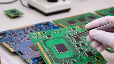
Choosing the right pcb board is rarely a simple purchasing decision. Global buyers compare electrical performance, manufacturing quality, delivery stability, and total ownership cost. A board that works well in a laboratory may fail under heat, vibration, moisture, or continuous industrial use.
This guide examines ten widely used PCB board types across consumer electronics, automotive systems, medical equipment, telecommunications, and industrial controls. It considers single-sided, double-sided, multilayer, rigid, flexible, rigid-flex, metal-core, HDI, ceramic, and high-frequency boards. Each type serves a different design purpose. Layer count, substrate material, copper thickness, impedance control, and thermal behavior can change the final result.
Practical sourcing experience shows that specifications alone do not guarantee reliability. Supplier process control matters. So do inspection records, traceability, testing capacity, and communication during revisions. A low quotation can become expensive after redesigns, delays, or field failures. This is often underestimated. Buyers should verify certifications, sample results, production tolerances, and environmental requirements before placing larger orders.
The following overview offers a balanced starting point for technical teams, purchasing managers, and distributors. It does not treat one board type as universally superior. Real projects are less tidy. A flexible board may solve space problems but complicate assembly. A ceramic board may handle heat better but require a higher budget. Careful comparison remains essential when performance, compliance, and long-term supply reliability matter.
Top 10 PCB Board Types for Global Buyers
IPC-2221C classes describe expected performance, not a simple list of board shapes. Class 1 suits general products with limited service demands. Class 2 supports dedicated equipment requiring consistent performance and longer operating life. Class 3 targets high-reliability systems, where defects, vibration, or intermittent connections can create serious consequences. The classification must match the product’s real operating environment.
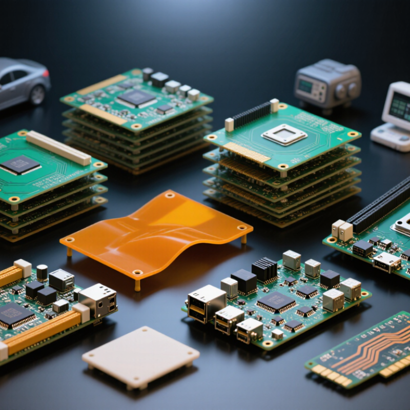
The top ten board types are single-sided, double-sided, multilayer, rigid, flexible, rigid-flex, HDI, metal-core, ceramic, and high-frequency boards. A single-sided board may fit a simple control panel, while a multilayer board can route dense processor signals through eight or more layers. Flexible boards bend around hinges. Metal-core boards move heat beneath powerful lighting circuits. Ceramic boards tolerate demanding thermal conditions. HDI boards use microvias for compact layouts. These categories can overlap, so selecting only by name is risky. I still recheck layer counts, bend radius, thermal paths, and Class 3 inspection needs before approving a design.
Tips: Ask for the supplier’s stack-up, material data, impedance results, and inspection records. Confirm whether the quoted class covers the finished assembly, not just the bare board. Small gaps matter. A low-cost Class 2 choice may become expensive after field failures. Also, IPC-2221C guidance is not a substitute for application testing; temperature cycling and vibration testing may reveal weaknesses that drawings miss.
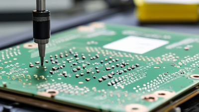
Rigid PCBs remain the practical foundation for many control, industrial, and communication products. They can range from one to 32 copper layers, depending on routing density and power requirements. Layer count alone does not prove quality.
FR-4 materials offer a useful balance of cost, stiffness, and electrical performance. However, not every FR-4 laminate behaves the same way during heat exposure. Buyers should review glass transition temperature, copper weight, dielectric thickness, and moisture requirements. A dense 16-layer board may need controlled impedance, sequential pressing, and careful thermal planning. Small details matter.
IPC-6012 provides performance and qualification criteria for rigid printed boards. It supports checks for dimensions, plating, hole quality, electrical integrity, and workmanship. Specify the required acceptance class before requesting quotations. Ask for evidence. Useful records include material certificates, microsection reports, electrical test results, and inspection data for annular rings and plated hole walls.
A reliable purchasing process also compares the fabrication drawing with the supplier’s stack-up proposal. I have seen low-cost quotations change copper thickness without clear notice. That gap matters. Confirm finished board thickness, surface finish, solder mask coverage, and allowable tolerances in writing. The exact layer count may still be wrong for the application. A simpler eight-layer design can outperform a poorly planned twelve-layer board. Review thermal paths, connector stress, and assembly yield before approval. IPC-6012 is important, but it cannot replace a complete design review and traceable inspection plan.
| No. | Rigid PCB Type | Layer Count | Typical Material | Typical Finished Thickness | Typical Copper | Typical Minimum Trace / Space | Common Applications | IPC-6012 Considerations |
|---|---|---|---|---|---|---|---|---|
| 1 | Single-Sided Rigid FR-4 PCB | 1 | Standard FR-4, Tg typically 130–150 °C | 0.8–1.6 mm | 18–35 µm finished | 0.15–0.20 mm | Simple controls, indicators, low-density consumer electronics | Specify board class, conductor dimensions, solderability, cleanliness, and dimensional requirements. |
| 2 | Double-Sided Through-Hole PCB | 2 | FR-4 with plated through-holes | 1.0–2.0 mm | 18–35 µm finished | 0.15–0.20 mm | Power supplies, industrial controls, connectors, embedded systems | Verify plated-hole reliability, hole size tolerances, annular rings, and copper plating requirements. |
| 3 | 4-Layer Standard Multilayer PCB | 4 | FR-4, Tg typically 130–170 °C | 1.0–1.6 mm | 18–35 µm finished | 0.10–0.15 mm | Microcontrollers, communication modules, instrumentation | Control layer registration, dielectric spacing, impedance requirements, and via integrity should be defined. |
| 4 | 6-Layer Signal-and-Power PCB | 6 | FR-4 with dedicated power and ground planes | 1.2–1.8 mm | 18–35 µm finished | 0.10–0.15 mm | Industrial networking, motor control, computing hardware | Confirm layer-to-layer registration, dielectric thickness, controlled impedance, and thermal stress testing. |
| 5 | 8-Layer High-Density Rigid PCB | 8 | High-Tg FR-4, typically Tg 170 °C or higher | 1.2–2.0 mm | 18–35 µm finished | 0.09–0.12 mm | High-speed digital equipment, gateways, medical instruments | Define Class 2 or Class 3 acceptance, impedance coupons, microsection criteria, and laminate compatibility. |
| 6 | 10–12-Layer High-Speed PCB | 10–12 | Low-loss or high-Tg FR-4 family material | 1.6–2.4 mm | 18–35 µm finished | 0.075–0.10 mm | Servers, routers, test equipment, advanced control systems | Impedance tolerance, resin distribution, skew control, via reliability, and dimensional stability are key. |
| 7 | 14–16-Layer Complex Multilayer PCB | 14–16 | High-Tg FR-4 with controlled dielectric construction | 1.8–2.8 mm | 18–35 µm finished | 0.075–0.10 mm | Data acquisition, automation, telecommunications, advanced computing | Specify registration limits, multilayer lamination quality, thermal cycling, CAF resistance, and electrical testing. |
| 8 | 18–24-Layer Backplane or Processor PCB | 18–24 | High-Tg FR-4 or low-loss multilayer material | 2.0–3.2 mm | 18–70 µm finished | 0.075–0.10 mm | Backplanes, processor boards, high-channel-count systems | Pay particular attention to bow and twist, hole-wall quality, impedance consistency, and multilayer registration. |
| 9 | 26–32-Layer Ultra-Complex Rigid PCB | 26–32 | High-Tg FR-4 or application-specific low-loss laminate | 2.4–4.0 mm | 18–70 µm finished | 0.075–0.10 mm | Large computing platforms, networking chassis, complex instrumentation | Use a detailed fabrication drawing covering stack-up, coupons, testing, lamination, registration, and Class 3 requirements where applicable. |
| 10 | Heavy-Copper Rigid FR-4 PCB | 1–12 | FR-4 or high-Tg FR-4 with thick copper layers | 1.6–4.0 mm | 70–400 µm finished | 0.20–0.50 mm | Battery systems, power conversion, automotive and industrial power equipment | Specify copper weight, thermal requirements, plated-hole filling, etch compensation, current capacity, and thermal cycling. |
Note: Values are typical purchasing ranges for rigid PCB design and sourcing. Final capabilities depend on the approved fabrication drawing, stack-up, material system, board size, copper distribution, surface finish, and required IPC-6012 performance class.
Top 10 PCB Board Types for Global Buyers: Flexible PCBs and IPC-6013 Bend Requirements
Flexible PCBs with finished thicknesses from 0.05 to 0.30 mm suit compact sensors, cameras, and folded displays. However, thin does not automatically mean flexible. Copper weight, dielectric selection, coverlay, layer count, and stiffener placement all affect bending performance.
IPC-6013 provides qualification and performance requirements for flexible and rigid-flexible circuits. It does not define one universal bend radius for every design. The product drawing should state the intended bend area, bend direction, cycle count, and minimum radius. Static folds and repeated dynamic bends require different evaluations. A practical design review checks copper traces near the neutral axis and avoids sharp corners around vias. Smooth routing helps.
During supplier evaluation, request the finished thickness tolerance, material stack-up, bend test method, and inspection records. A nominal 0.10 mm circuit may become thicker near connectors or stiffeners. That local change can create unexpected stress. Ask for samples with the actual layer construction, not a simplified coupon. Bend them after assembly, because adhesive, solder, and component weight can change the result.
One detail is easy to overlook. IPC compliance alone cannot guarantee field life. Application temperature, vibration, folding speed, and storage conditions still matter. In some projects, designers choose 0.05 mm for space, then discover handling damage during assembly. That choice may need rethinking. Reliable sourcing depends on matching the declared bend requirement to real production conditions.
This chart compares estimated minimum bend radii for flexible PCBs across common total thicknesses. The values apply general engineering guidance of 10× thickness for static bending and 100× thickness for repeated dynamic bending. IPC-6013 defines qualification and performance requirements, while the final bend radius must also consider layer count, copper type, coverlay, stiffeners, and application conditions.
Rigid-flex boards rank among the most practical PCB choices for compact global products. Their rigid sections support components, while flexible zones replace cables and connectors. The global flexible PCB market was valued at about USD 19.2 billion in 2023, with strong growth projected through 2030, according to Grand View Research. That demand raises the need for controlled stackups, not simply thinner boards.
IPC-6016 provides qualification guidance for flexible and rigid-flex printed boards. Buyers should review layer symmetry, coverlay design, copper thickness, and bend-zone geometry. A bend zone should exclude vias, pads, and sharp copper corners. IPC-TM-650 test methods support evaluation of thermal stress, solderability, insulation resistance, and mechanical durability. Practical testing should include repeated flexing, thermal cycling, humidity exposure, and cross-section inspection. One test is never enough. Real products often fail at transitions.
Tips: Keep the first bend outside component areas. Use larger bend radii than the minimum drawing value. Ask for stackup drawings before quoting. The 2024 flexible PCB market analysis from Grand View Research identifies consumer electronics and automotive systems as major demand sectors. These applications often require thousands of movement cycles. Specify the cycle count, temperature range, and bend radius together. A common mistake is approving the material separately from the finished geometry. That decision deserves a second review.
Among the top ten PCB types, HDI boards serve designs where space, signal speed, and layer efficiency matter most. Fortune Business Insights valued the global PCB market at approximately USD 89.7 billion in 2023. Its forecast points toward continued growth through 2032, driven by compact electronics and high-density computing. HDI supports this shift through sequential build-up layers, fine traces, and laser-drilled microvias. Microvias at or below 150 μm can shorten electrical paths and release valuable routing space. They also demand tighter process control.
IPC-2221C offers baseline guidance for clearances, conductor geometry, dielectric spacing, and high-density layout decisions. It should guide the design, not replace stack-up testing or fabricator feedback. A 150 μm microvia may look acceptable in CAD. It can still fail during plating, thermal cycling, or registration checks. Practical reviews should confirm via capture-pad size, aspect ratio, resin filling, copper thickness, and impedance targets. IPC-6016 adds useful qualification guidance for HDI fabrication. The standard alone is not enough.
Field experience shows that smaller vias increase inspection sensitivity. Cross-sections often reveal voids that automated electrical tests miss. That detail is easy to underestimate. The 2024 IPC electronics industry outlook also reflects persistent pressure for higher reliability and shorter production cycles. Therefore, global buyers should request capability data, cross-section evidence, and controlled material specifications before approving an HDI supplier. A smaller microvia is not automatically a better microvia.
| Cookie | Duration | Description |
|---|---|---|
| cookielawinfo-checkbox-analytics | 11 months | This cookie is set by GDPR Cookie Consent plugin. The cookie is used to store the user consent for the cookies in the category "Analytics". |
| cookielawinfo-checkbox-functional | 11 months | The cookie is set by GDPR cookie consent to record the user consent for the cookies in the category "Functional". |
| cookielawinfo-checkbox-necessary | 11 months | This cookie is set by GDPR Cookie Consent plugin. The cookies is used to store the user consent for the cookies in the category "Necessary". |
| cookielawinfo-checkbox-others | 11 months | This cookie is set by GDPR Cookie Consent plugin. The cookie is used to store the user consent for the cookies in the category "Other. |
| cookielawinfo-checkbox-performance | 11 months | This cookie is set by GDPR Cookie Consent plugin. The cookie is used to store the user consent for the cookies in the category "Performance". |
| viewed_cookie_policy | 11 months | The cookie is set by the GDPR Cookie Consent plugin and is used to store whether or not user has consented to the use of cookies. It does not store any personal data. |