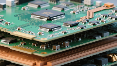
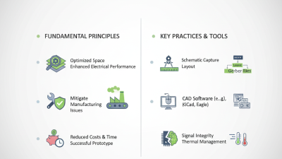
In 2026, choosing the best circuit board design will depend less on fashion and more on measurable product demands. A compact medical sensor, a high-speed AI server, and an electric vehicle inverter cannot share the same board strategy. Their heat, signal integrity, mechanical stress, and certification requirements are fundamentally different.
Industry forecasts show why this decision matters. WSTS projects the global semiconductor market will reach approximately $762.7 billion in 2026, following continued growth in data processing, automotive electronics, and connected devices. More chips usually mean tighter routing, faster interfaces, and greater power density. Prismark’s PCB market analysis also points toward sustained growth in advanced boards, including high-density interconnect and rigid-flex technologies. These figures do not prove that HDI is always superior. They indicate rising design pressure.
Performance comes first.
This guide compares multilayer, HDI, rigid-flex, and conventional two-layer designs for real 2026 applications. IPC technology roadmaps emphasize controlled impedance, miniaturization, thermal management, and manufacturing reliability. Those priorities should influence every layout decision, from via structures to copper thickness. A four-layer board may outperform HDI when production volume is modest and serviceability matters. Conversely, HDI can be justified when a wearable device needs fine-pitch components inside a narrow enclosure. Rigid-flex may reduce connectors, but it can introduce bending, material, and assembly risks. I should acknowledge one limitation: market reports describe broad trends, not the exact constraints of your product. The best design emerges from testing, supplier feedback, field experience, and disciplined cost analysis.
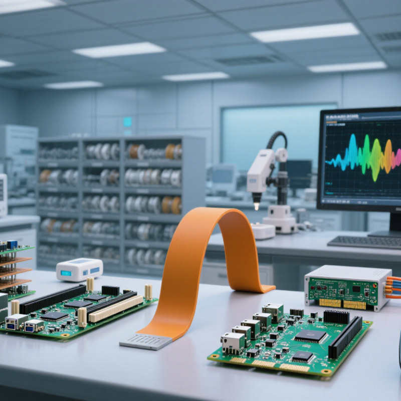
Circuit board design types serve different engineering problems. Rigid boards offer mechanical stability, predictable assembly, and lower unit cost. They suit control modules, industrial equipment, and fixed enclosures. Flexible boards bend around hinges and narrow spaces. Their lighter wiring can reduce connectors, but repeated bending still demands careful radius control. Rigid-flex boards combine both structures. They reduce cable assemblies, yet their fabrication and inspection costs are higher.
HDI boards use microvias and fine lines to create dense routing in compact products. They support smaller packages and shorter electrical paths. High-frequency boards focus on controlled impedance, low signal loss, and stable dielectric behavior. They matter in radar, wireless, and fast data systems. A 2024 market report from Grand View Research estimated the global PCB market at about 89.7 billion dollars in 2023, with growth near 5.6% annually through 2030. That expansion favors advanced designs, but not every product needs them.
The best type depends on heat, motion, space, signal speed, and service access. For a stationary controller, rigid construction may remain the wiser choice. For a wearable device, flexible or rigid-flex designs can remove bulky connectors. I would not select HDI only because it sounds future-ready. That assumption is tempting, but incomplete. Early prototypes should test bending, thermal cycling, impedance, and repair time. IPC’s 2024 technology roadmap also emphasizes higher density and thermal control, though real production data can expose overlooked weaknesses. Cost models deserve another review.

The best circuit board design in 2026 will depend on operating conditions, not novelty. WSTS’s Spring 2025 Forecast projects semiconductor sales growth of 11.2% in 2025 and 8.5% in 2026. That expansion will increase pressure on density, signal integrity, thermal control, and production capacity. Still, volume alone should not dictate the stack-up.
For compact products, HDI boards can shorten signal paths and support finer component spacing. They require tighter process control and higher inspection costs. Multilayer rigid boards remain practical for power equipment, industrial controllers, and stable high-speed routing.
Rigid-flex designs suit moving assemblies, where cables create failure points. They cost more, though. A perfect stack-up rarely exists.
Grand View Research estimated the global PCB market at about 89.7 billion US dollars in 2023, with continued growth expected through 2030. This suggests stronger demand, but not unlimited manufacturing flexibility. Engineers should check material availability, layer count, impedance control, thermal expansion, and repair access before selecting a design type. IPC standards provide useful guidance for design, fabrication, and acceptance criteria.
In real projects, early fabrication feedback often changes the first layout. That is not failure. It is evidence. A cheaper two-layer board may become expensive after shielding, heat sinks, and redesigns are added. Conversely, an advanced HDI board may solve density problems but create yield risks. The right choice balances electrical performance, lifecycle cost, reliability, and manufacturability.
Choosing the best circuit board design in 2026 depends less on fashion and more on physical demands. In practical design reviews, I compare rigid, flexible, and rigid-flex boards against movement, space, heat, and service needs. Rigid boards remain dependable for fixed equipment, control panels, and compact modules. They provide stable support for soldered components and are usually easier to inspect. They are predictable. Their fixed shape, however, can require extra connectors, cables, or awkward mounting brackets.
Flexible circuit boards solve tight routing problems. They can bend around a camera housing, fold beneath a display, or pass through a narrow hinge. This saves space and may reduce assembly weight. Yet repeated flexing can damage copper traces if the bend radius is too small. A prototype may survive ten folds, then fail after months of vibration. That detail is easy to miss. I would not approve a flexible design without testing bend cycles, crease zones, and nearby component stress.
Rigid-flex boards combine firm component areas with bendable interconnects. They can remove several connectors and shorten signal paths, which helps in medical instruments, wearables, and compact industrial sensors. The design is less forgiving, though. Layer transitions, stiffeners, and controlled bend areas require careful documentation and experienced inspection. My first preference is often rigid-flex for crowded products. That preference can be wrong when repair access, low volume, or a simple flat layout matters more. A cheaper rigid board may perform better in real service conditions.
This engineering comparison uses a typical 0–10 design-fit index synthesized from common characteristics: dimensional stability, bendability, routing density, assembly integration, and suitability for compact products. Rigid-flex boards provide the strongest overall balance, while rigid boards remain the most stable and cost-efficient for fixed assemblies. Flexible boards are best when repeated bending, weight reduction, or three-dimensional packaging is the main requirement.
What Is the Best Circuit Board Design Type for 2026?
The best circuit board design in 2026 will depend on the technology inside the product. Artificial intelligence devices need fast signal paths, compact layouts, and controlled heat. High-speed communication equipment may require low-loss materials and careful impedance control. These demands often favor high-density interconnect or advanced multilayer boards. However, density alone is not a reliable answer.
Flexible and rigid-flex boards can support wearable sensors, compact robotics, and moving assemblies. Their reduced cable count can improve reliability in tight spaces. Power conversion systems need wider copper, stronger thermal paths, and greater clearance. A board that works well for an edge processor may fail inside a high-current module. I have seen attractive layouts become difficult to assemble because testing access was considered too late. That mistake remains common.
Tips: Define bandwidth, temperature, current, and mechanical movement before choosing the board type. Review thermal images from early prototypes, not only simulation results. Ask manufacturers about drilling limits, material availability, and inspection capability. Keep critical traces short and separated from noisy power sections. Flexible designs need controlled bending zones. Rigid designs need realistic expansion planning. Cost estimates should include testing and rework. Emerging technology changes quickly, so leaving limited design space for upgrades can be valuable. It may also increase board size, which is an uncomfortable trade-off.
Comparative selection guide based on typical 2026 engineering requirements, including signal speed, thermal density, power conversion, miniaturization, manufacturing complexity, and sustainability.
| Circuit Board Design Type | Primary Technology Driver | Typical 2026 Applications | Recommended Layer Range | High-Speed Capability | Thermal Management Need | Miniaturization Potential | Manufacturing Complexity | Best Selection Scenario |
|---|---|---|---|---|---|---|---|---|
| Advanced HDI Multilayer PCB | AI edge computing, high-density processors, advanced memory, and compact connectivity modules | Edge AI devices, industrial controllers, networking equipment, robotics, and compact computing systems | 8–20 layers; microvias and sequential build-up commonly required | High Suitable for multi-gigabit differential links when impedance and return paths are controlled |
Medium to high; thermal vias, copper planes, heat spreaders, and airflow planning are often needed | Very high | High | Best general-purpose choice for dense digital products with limited board area |
| High-Speed Low-Loss Multilayer PCB | 112G-class signaling, high-speed memory, optical-electrical interfaces, and advanced data processing | Data-center hardware, high-performance computing, network switching, test equipment, and accelerator platforms | 10–32 layers; low-loss dielectric materials and tightly controlled stackups are typical | Very high Designed for low insertion loss, controlled impedance, crosstalk reduction, and timing integrity |
High; power density and processor heat often require dedicated thermal structures | Medium | Very high | Best for bandwidth-first systems where signal integrity is more important than low cost |
| Rigid-Flex PCB | Wearable electronics, robotics, foldable assemblies, and reduced cable-count architectures | Medical instruments, compact sensors, robotic joints, aerospace electronics, and portable devices | 2–12 rigid layers with 1–6 flex layers, depending on bend and routing requirements | Medium to high Suitable for controlled high-speed paths when bend zones and impedance are carefully designed |
Medium; flex areas have limited copper and heat-spreading capability | Excellent | High | Best when mechanical movement, space reduction, or connector elimination is critical |
| Metal-Core or Heavy-Copper PCB | High-power conversion, electrification, motor control, and LED thermal dissipation | Power supplies, battery systems, motor drives, lighting equipment, charging equipment, and industrial controls | 1–6 layers; copper thickness may range from standard foil to several hundred micrometers | Low to medium Optimized primarily for power delivery rather than dense high-speed routing |
Very high Metal cores and heavy copper improve heat spreading and current capacity |
Low | Medium | Best for high-current, high-temperature, or thermally constrained power electronics |
| Embedded-Component PCB | Higher functional density, shorter interconnects, and reduced assembly footprint | Miniature medical products, sensor nodes, secure modules, high-density industrial electronics, and compact communications hardware | 4–16 layers; passive or selected active components may be embedded within the substrate | High Shorter electrical paths can improve parasitic performance and reduce interconnect length |
Medium to high; embedded heat sources can be difficult to inspect and cool | Very high | Very high | Best when board area, electrical path length, and package height must all be minimized |
| RF and Microwave PCB | 5G/6G research, radar, satellite links, sensing, and millimeter-wave communications | Radar sensors, wireless infrastructure, satellite equipment, industrial imaging, and precision measurement systems | 2–12 layers; specialized laminates, grounded coplanar structures, and RF shielding may be used | Very high Designed for controlled dielectric properties, low loss, isolation, and stable phase behavior |
Medium; localized power amplifiers may require thermal vias or metal-backed structures | Medium | High | Best for wireless, radar, and microwave products where RF performance dominates design selection |
| Power-Integrity-Optimized Multilayer PCB | AI processors, fast transient loads, distributed power architectures, and energy-efficient computing | Embedded computing, industrial automation, networking systems, robotics, and intelligent control platforms | 6–18 layers with closely coupled power-ground planes and dedicated voltage-regulator regions | High Supports low-inductance power distribution and improved transient response |
High | Medium to high | Medium to high | Best when processor stability, power noise, and fast load changes are major risks |
| Flexible PCB | Ultra-compact sensing, wearable products, dynamic movement, and lightweight interconnects | Wearables, biomedical sensors, cameras, compact displays, battery packs, and moving assemblies | 1–6 conductive layers; single-sided, double-sided, or multilayer flex constructions are common | Medium Appropriate for moderate-speed interfaces with controlled bend radius and grounding |
Low to medium | Excellent | Medium to high | Best for lightweight products requiring bending, folding, or three-dimensional routing |
| Sustainable and Repair-Oriented PCB | Material reduction, lifecycle extension, repairability, recycling, and lower manufacturing waste | Industrial equipment, appliances, transportation electronics, modular instruments, and long-service products | 2–12 layers; standardized materials, replaceable modules, and accessible components are favored | Medium Performance depends on the selected stackup and component architecture |
Medium; serviceable thermal interfaces can simplify maintenance and replacement | Medium | Low to medium | Best when total lifecycle cost, repair access, material efficiency, and regulatory goals matter |
Note: Layer counts, speed classifications, and complexity levels are indicative engineering ranges rather than universal limits. The final selection should be validated through stackup simulation, signal-integrity analysis, thermal analysis, manufacturability review, reliability testing, and applicable safety requirements.
Choosing the best circuit board design starts with the application, not the board name. A fixed industrial controller may benefit from a rigid multilayer board. It offers stable support, predictable assembly, and efficient heat spreading. Wearable devices need different priorities. Flexible boards can follow tight bends and reduce wiring space. Mixed mechanical structures often suit rigid-flex designs. That choice matters.
High-speed equipment requires controlled impedance, short return paths, and a carefully verified layer stack. Dense packages may require HDI features, but higher density can increase inspection and manufacturing risks. Power circuits need suitable copper weight, wider traces, and thermal paths near heat-producing components. In practical design reviews, engineers should examine enclosure movement, connector stress, moisture, cleaning chemicals, and expected service temperature. Do not design in isolation.
Reliability also depends on production capability. A beautiful layout may fail when its tolerances exceed the fabricator’s process limits. Test points, inspection access, and repair space deserve attention early. Recognized industry standards can guide material selection, spacing, testing, and acceptance criteria. I have sometimes favored compact layouts too quickly, then discovered that assembly access was poor. That lesson remains useful. The best design may be slightly larger, easier to test, and more tolerant of real-world handling. Engineers should document these compromises and verify them through prototypes, thermal checks, signal measurements, and mechanical trials.
| Cookie | Duration | Description |
|---|---|---|
| cookielawinfo-checkbox-analytics | 11 months | This cookie is set by GDPR Cookie Consent plugin. The cookie is used to store the user consent for the cookies in the category "Analytics". |
| cookielawinfo-checkbox-functional | 11 months | The cookie is set by GDPR cookie consent to record the user consent for the cookies in the category "Functional". |
| cookielawinfo-checkbox-necessary | 11 months | This cookie is set by GDPR Cookie Consent plugin. The cookies is used to store the user consent for the cookies in the category "Necessary". |
| cookielawinfo-checkbox-others | 11 months | This cookie is set by GDPR Cookie Consent plugin. The cookie is used to store the user consent for the cookies in the category "Other. |
| cookielawinfo-checkbox-performance | 11 months | This cookie is set by GDPR Cookie Consent plugin. The cookie is used to store the user consent for the cookies in the category "Performance". |
| viewed_cookie_policy | 11 months | The cookie is set by the GDPR Cookie Consent plugin and is used to store whether or not user has consented to the use of cookies. It does not store any personal data. |